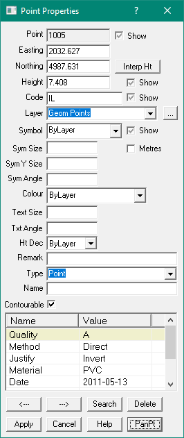
Point Properties
This option allows the user to change the properties of one or more points.
If multiple points are selected, the changes are applied to all the points.
This makes it easy to change the symbol or layer of a whole set of points at once.
Point Number
The point number can be any point number in the range of points allowed for the job.
The maximum point number is set in the File\Job Settings option.
This option does not allow the point number to be changed, use the Renumber option.
The Show check box controls whether the point number is displayed on the screen.
Easting and Northing
Every point must have an Easting (X) value, it is stored to more than 6 decimal places but
only displayed to three decimal places. You can see the Easting (X) and Northing (Y) value
for the mouse displayed in the bottom left of the screen as you move the mouse.
Interp Ht
This button computes a height value for the point(s) from the triangles if the point does not
already have a height associated with it.
Height
The height (Z) value for the point is optional. If a point has no height value, this field will be blank.
Computed points like lot corners will generally not have a height value.
The height value is stored to more than 6 decimal places but only displayed to three decimal places.
The Show check box control whether the point height (RL) is displayed on the screen.
Code
The point code is a text string which is associated with the point.
Generally this will be entered during the field survey to indicate what type of point feature
is being measured. e.g. a code ‘FC01’ may be used to tag a point on a fence line (fence line 1).
The code can consist of alpha and numeric characters, it can be of any length, but generally is
less than 10 characters long. The Show check box control whether the point code
is displayed on the screen.
You can assign the symbol automatically by the code, see Code Processing.
Layer
Select the layer on which the point(s) reside. See Layers for more details on how
layers work. When editing point properties for multiple points, if they are on different layers
the layer will be shown as * Various, if that is not changed, the points are
left on their current layers. If a new layer is selected, all the selected points are moved
onto the new layer.
Symbol
The symbol is chosen from a list and control the diagrammatic symbol drawn as the point.
The list of available symbols is controlled by the library file, see the File\Job Settings option.
The Show check box control whether the point symbol is displayed on the screen.
If the ByLayer option is chosen, the actual symbol drawn will be the symbol for the layer on
which the point(s) reside.
You can assign the symbol automatically by the code, see Code Processing.
Symbol Size
Enter the symbol size in mm, or if 'Symbol in Metres' is ticked enter it in metres.
If defined in mm the actual plotted size is scaled by the current screen size and the Job Plot Scale.
If left blank, it will use the Layer symbol size.
Symbol in Metres
When unticked - the symbol size is in mm at the job plot scale.
When ticked - the symbol size is in metres at current scale.
Symbol Y Size
You can enter a different Y size to the Symbol Size above to differentially scale the symbol.
Enter the symbol size in mm, or if 'Symbol in Metres' is ticked enter it in metres.
If defined in mm the actual plotted size is scaled by the current screen size and the Job Plot Scale.
Leave it blank if you don't know what to do here.
Symbol Angle - Bearing
Enter the symbol survey bearing. The value is in degrees, zero being North.
Symbol Colour
Select the symbol colour from the list. If the ByLayer option is chosen, the actual colour
drawn will be the colour for the layer on which the point(s) reside. Click here for Colour chart.
Text Size
Enter the text size in mm of the point number, height and code. Note that the actual plotted
size is scaled by the current screen size and the Job Plot Scale.
Text Angle
Enter the text angle as a survey bearing, 0 degrees is North.
Height Decimal Places
Enter a number 1-4 as the number of decimal places displayed in the height value for the point.
If the ByLayer option is chosen, the actual number of decimal places drawn will be the number of
decimal places for the layer on which the point(s) reside.
Remark
Each point may have a remark attached. this is generally taken from the field data recorder and
contains field notes about the point.
Type
Select the point type from the list.
Name
A point can have a name. e.g. for a state survey mark, the control point name can be entered.
Contourable
Uncheck this box if the point is not to be used for contours.
Check the box if you want it to be used for contours.
If this box is greyed out, the Layer controls the Contourability of the point.
Note: Only Contourable points (ticked) will be used to form triangles (TIN, DTM)
| Point Layer | Point | Used in Triangles |
| Contourable | Contourable | Yes |
| Contourable | Non Contourable | No |
| Non Contourable | - | No |
The Layer setting over-rides the point setting
Extra Attributes
Extra Attributes are displayed in a scrollable 'Name-Value' list.
You can directly edit the values.
To add a value type in the name and value into a spare row at the bottom of the list
To delete a value, just erase the name
You can only edit the extra attributes if ONE point is selected.
Delete
Press this button to delete the selected point(s).
Clear
This button un-selects all points and then allows you to enter a point number for display.
Displaying Points
To display a point (enter points mode) and double click on the point, or click once on the point
and press the Properties button. To select multiple points, hold down the Shift or Ctrl keys and
click on more points. When the properties button is pressed the points properties will be displayed.
Display of Multiple Points
When multiple points are selected and displayed, the value will be marked as ‘* Various’ if the
points have different values. If say two points are selected, and a height of ‘* various’ is
displayed, that means that the points have different heights. If the height displayed is say ‘125.000’,
that means BOTH points have the same height.
If points have different values, you can select a single value to be applied to all selected points.
This is an easy way to apply a single value to a range of points.
North Point Symbol
To display a North Point, create a point in the job where you want the North Point displayed.
Set that Point to a Symbol for the North Point, say 6, or Nth.
Now set the symbol size = say 25 (mm)
And set the Angle to 0 (degrees).
This symbol will be darw to point to 0 degrees (North) whatever the viewport orientation.
If you'd like to define your own North Point Symbol, edit the xml config file.
The standard config file has a symbol 'NTH' at about line 1112.
For More info on editing trhe XML file see here.